I bought a cheap Zynq board! It's not very good.
See this GitHub repo - it's the control board from some bitcoin miner.
The main problem I have with it is that it's not very easy to get power into, and the IO connector is a 2mm pitch one, instead of the much more common 2.54mm pitch.
So... I made up a board to adapt the 2mm IO headers to standard 2.54mm headers, as well as 5 standard PMOD headers - board files will be up somewhere when I've made sure it works. It can take 5v/12v input with a step down to 3.3v for the PMODs, with ~2A available. This is probably overkill but it works.
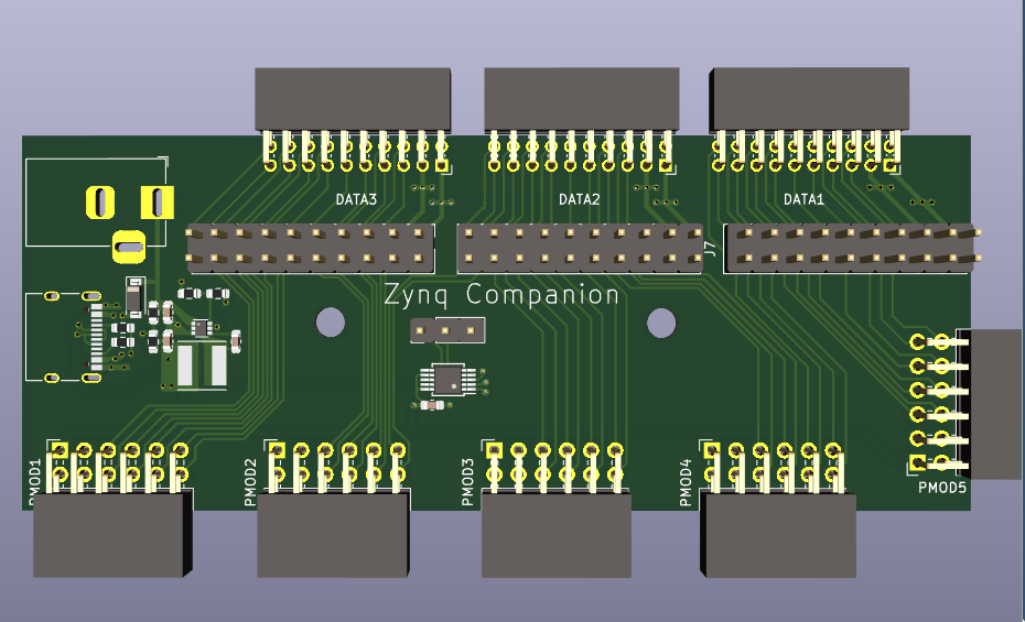
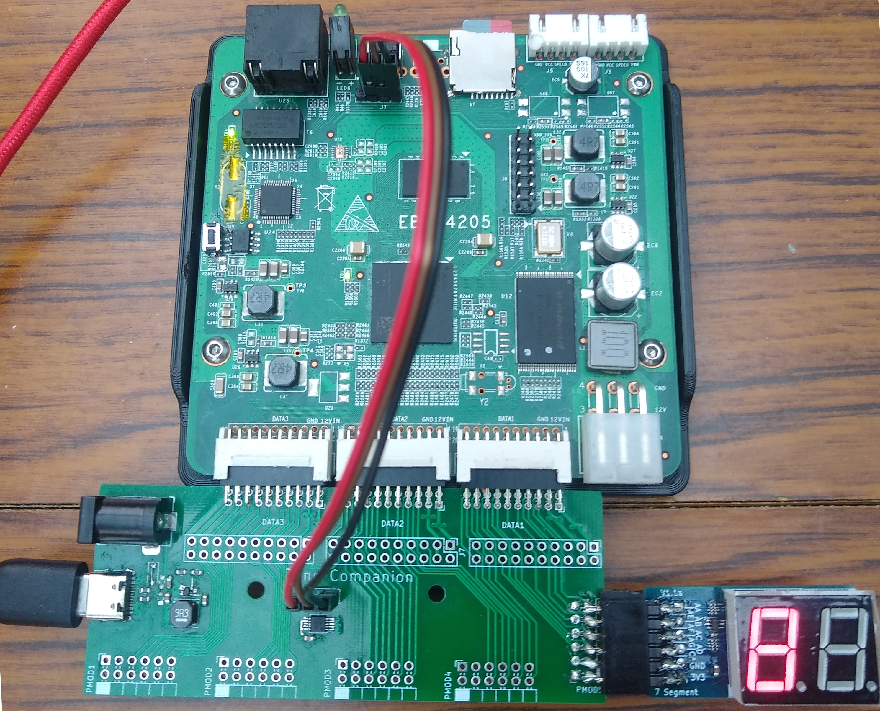
The PCBs are in, and I soldered a first prototype. After much fighting against Vivado, it works! It provides 5 PMOD connectors from the user IO, and a USB to serial converter that can be attached to the on-board UART.
I used the XDC from the repo linked above for the user IOs, and this example Vivado project to build a working bitstream using Vivado along with the Xilinx tutorial to build it into a boot image (with standalone ARM application).
One issue I had is that the regulator package I picked is much smaller than I expected - I had trouble soldering it without shorts. The reg I picked comes in 2 packages - SOT563 (which I used) and TSOT26 (which is a lot bigger).
The other thing is that initially, I had a diode between the (normally 5v) USB and barrel jack input, but then the input voltage wasn't high enough after going through the protection diode on the Zynq board. After bridging the spot where my diode goes it powered up fine!
I also added a reset button to the Zynq board (middle left) - the reset supervisor IC has a "manual reset" input on pin 1 that just needs connecting to GND through a button.