The board
This project happened mostly by accident - I wanted to design a small ESP board with mounting holes / LiPo charger, and I decided to stick a temperature sensor on it. I initially chose the SHTC3, because it wasn't too expensive (£1), and it had good specs. However, later on, I wasn't able to solder it consistently. Instead, I added a DHT22 temp/humidity sensor on a seperate breakout board and connected it with wires.
It features a buck converter rather than a simple linear regulator for greater efficiency, and also because the lowest dropout voltage I found in a linear regulators with 1A rating has been about 0.4v. This means it needs at least 3.3 + 0.4 = 3.7 volts to operate, but a single LiPo will be under this voltage about half of the time! I chose the TLV62568 buck converter, mainly because it was the cheapest one at quantity 1 on Digi-Key at the time.
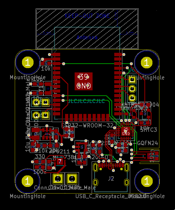
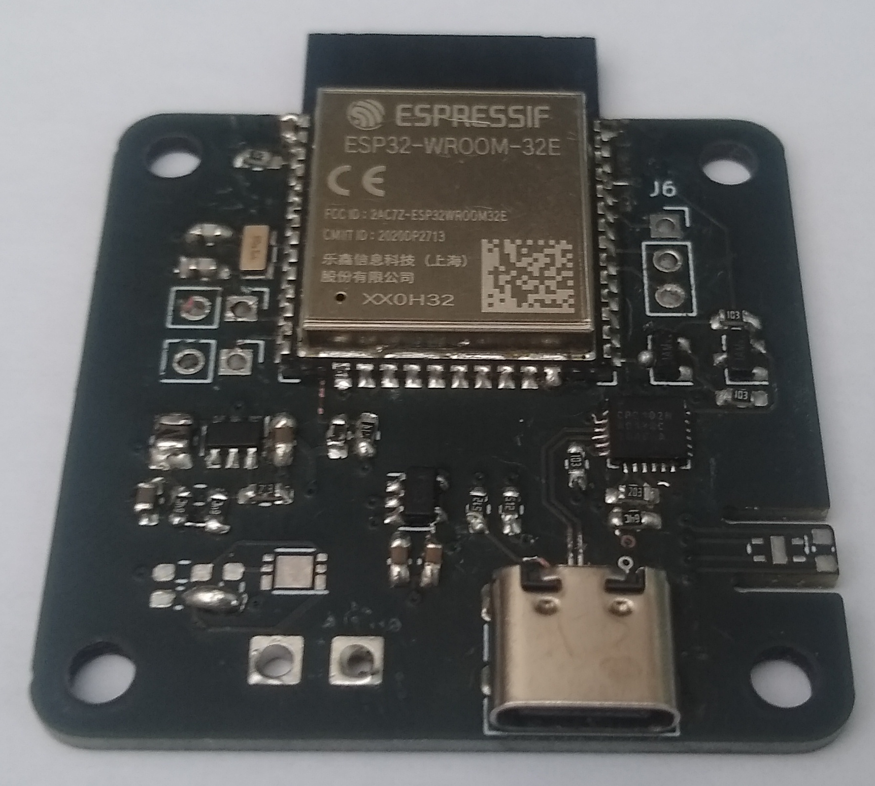
I made a few mistakes as it was targeting JLCPCB's 4 layer offer ($2 for a 4 layer board under 50mmx50mm) and they advertised it as ending on 25 Dec - namely, I forgot to add decoupling capacitors for the ESP32! I added one between the pins on the module, and it seems to be fine. Also, the JLC offer still stands, so I didn't have to rush it at all...
I also didn't manage to get the crystal oscillator working - my best guess so far is that I have the wrong load capacitance, meaning the crystal doesn't oscillate.
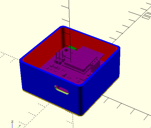
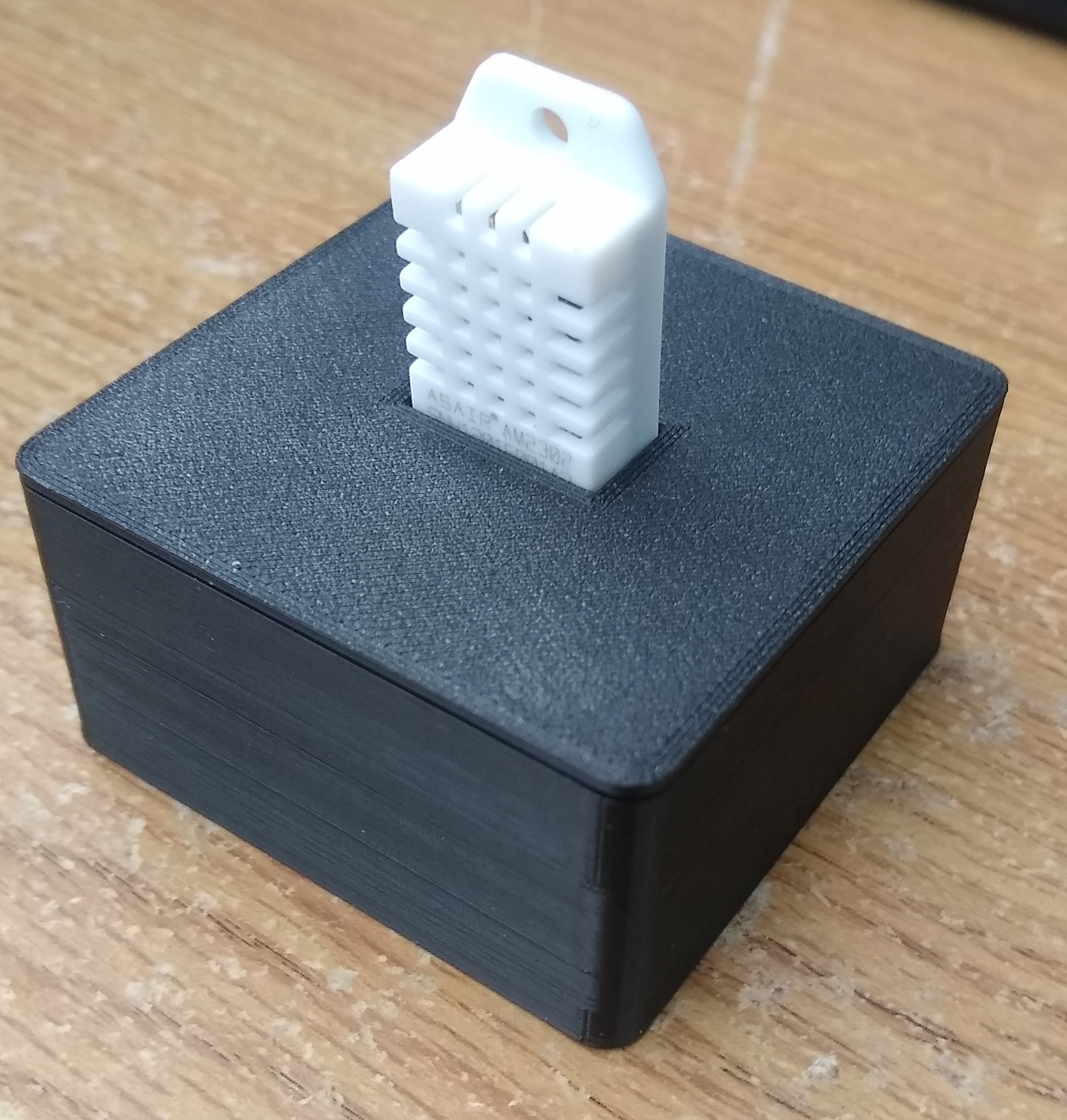
The case
I designed a case with OpenSCAD - it seems quite useful, definitely worth it for smaller/simpler designs.
Software
The software can be found on my GitHub: https://github.com/Stary2001/esp32-thing-fw
At the moment, it's hardcoded to one temp/humidity sensor and uploads to both Influx and Home Assistant, with a hardcoded password for both. Eventually I'll make it more generic.
ESP-IDF is the official SDK for writing software for ESP32 chips - it has lots of functionality that I need out of the box, like HTTP and MQTT libraries. Much of this is based from the wifi/http/mqtt examples.
MQTT was used for integrating with Home Assistant - with the right configuration, the sensor can automatically advertise itself. https://www.home-assistant.io/docs/mqtt/discovery/ Just send a JSON document with the configuration as outlined in the relevant sensor type. For a temp/humidity sensor, the relevant type is Sensor: https://www.home-assistant.io/integrations/sensor.mqtt/.
I chose to build it in C with cJSON (included in ESP-IDF):
	cJSON_AddStringToObject(device_json, "name", "Some Device");
	cJSON_AddStringToObject(device_json, "identifiers", mac_str);

	cJSON_AddStringToObject(json, "name", s->name);
	cJSON_AddStringToObject(json, "unique_id", unique_id);
	cJSON_AddStringToObject(json, "state_topic", s->state_topic);
	cJSON_AddStringToObject(json, "unit_of_measurement", s->unit);
	cJSON_AddItemToObject(json, "device", device_json);
	cJSON_AddStringToObject(json, "device_class", s->class);
I also chose to use 3 different MQTT topics (and device entries) - one for each value (battery/temp/humidity), rather than a single topic with a JSON blob and the JSON template functionality. I'm not sure if that would be better, but possibly more efficient as it only has to send one message.
Current measurements
The ESP32 datasheet: RTC timer + RTC memory 10 µA
The buck converter datasheet: 35-µA Operating Quiescent Current
The DHT22 datasheet: 40-50uA in standby
My resistor divider: > 3.3V/ (20kohm + 90kohm) 30 microampere (current)
adding up to ... 10 + 35 + 45 + 30 = 120uA
Which means it can sleep for 1000mA * h / 120uA = 49 week, 4 day, 5 hour, 20 minute, 0 second on a 1000mAh battery. Clearly, this doesn't model the time WiFi is on, but it gives a rough idea.
Assuming WiFi is on for 2 seconds out of every 5 minutes, and that it uses 200mA while on (the ESP32 datasheet quotes 180mA for 802.11n transmit), > (1000mA*h / ((120uA * (5min - 2s)) + 200mA * 2s)) * 5min = 4 week, 16 hour, 27 minute, 8.492748 second
When measuring the current to the battery with my multimeter I'm getting anywhere between 80uA and 150uA... I'm not sure how accurate that is.